Remote Relay Unit
The Remote Relay Unit (RRU) is used at remote locations when it is desirable to control several large loads such as second service panels, hot tubs, electric furnaces or electric boilers by simply running low-voltage wire loads to the remote location instead of trying to run high-voltage, high-current wires back to the demand control unit. Please note: The following steps should be performed by a licensed electrician.
The RRU contains:
- Four double-pole, single-throw (DPST) relays.
- Relay coil wiring harnesses (one for each relay), and
- Relay coil wiring harnesses (for connecting remote relays to the controller board).
Note: RRUs are available with one to eight relays. The unit shown below is standard with 4 DPST-NC relays. (The second pole of each relay is not shown.)
Figure 1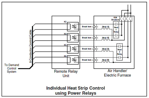
Hook-up
- Install the RRU at the desired location.
- Run #18AWG low-voltage wire from the demand control unit location to the location of the RRU. Use the same number of conductors as wires in the wire harness of the remote unit, two per relay.
- Wire-nut the low-voltage wires to the remote unit wire harness. Be sure to write down the wire color matchups.
- Wire to the contacts of the relays, just as you would if you were wiring the control unit as shown in Figure 1. You may need to refer to the particular unit’s installation manual or its appropriate Tech Tip to be sure this is correct. Always follow NEC and/or local codes.
- Attach the other end of the low-voltage wires to the harnesses supplied for attaching to the demand controller’s outputs.
- Attach the plugs to the logic board’s output jacks. Plug each remote relay’s plug into the desired control point jack on the controller’s logic board. To a large extent it does not matter which output relay jack the relay wires are plugged into since each output can be individually programmed with the desired priority. That said, it makes a lot of sense to put the relays in the normal order in which they will be shedding and restoring.
- You may move the relays already connected to the controller to other positions, if desired.
- See the table below for some possible combinations.
Caution
Do not common any relay wires together.
Switching Order
The Energy Sentry® RRU uses four DPST-NC relays with an 8-wire harness (two for each relay). These wires are tied into the main control unit via an 8-conductor, 18-gauge wire that connects to the control point output jacks on the controller board with the connectors provided. The switching order depends on the priority programmed for each auxiliary relay.
Remote Relay Unit: Examples of Priority Hook-ups
| Electric Furnace or Electric Boiler | ||||||||
|---|---|---|---|---|---|---|---|---|
| Last Shed | 24-hour control | First Shed | ||||||
| Relay | 1 | 2 | 3 | 4 | 5 | 6 | 7 | 8 |
| Load A | Dryer | A/C Compressor | Water Heater | 5kW Heat | 5kW Heat | 5kW Heat | 5kW Heat | 5kW Heat |
| Heat Pump with Individual Element Control | ||||||||
|---|---|---|---|---|---|---|---|---|
| Last Shed | 24-hour control | First Shed | ||||||
| Relay | 1 | 2 | 3 | 4 | 5 | 6 | 7 | 8 |
| Load A | Dryer | Heat Pump Compressor | Water Heater | 5kW Heat | 5kW Heat | 5kW Heat | 5kW Heat | |
for Metering