Control of Heat Pumps
A homeowner can control the electric output of their heat pumps with the use of Energy Sentry demand controller. Please note: The following steps should be performed by a licensed electrician and is not recommended for homeowners.
A generalized drawing is shown in Figure 1. These directions are only a general guide to the proper hookup of heat pumps and may vary depending on the specific equipment and installation. For controlling heat pumps with low voltage, only two signal (pilot duty) relays are required. This method of controlling heat works well in areas where there is only 10KW of strip heat. In areas where there is more than 10KW of strip heat in the air handler or electric furnace, it is strongly recommended to use individual control of the elements, by one of the next two methods.
Figure 1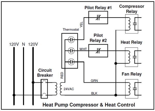
Hook-up (Compressor)
- Refer to the schematic on the compressor unit. Locate the low-voltage wire (Yellow wire or “Y” terminal) from the thermostat that signals the compressor relay to operate.
- Insert a control relay between the thermostat and the compressor relay as shown in Figure #1 above. This point can be found in the air handler unit, or at the condensing unit.
- Interrupt the signal found in Step 2 with the control relay using the normally-closed contact. Run the control relay’s coil wires back to the demand controller.
- Be sure to program the relay with a minimum OFF-TIME of at least 5 minutes to prevent short cycling of the compressor. Be sure to program a minimum ON-TIME of 6 to 9 minutes to maintain desired comfort. If the compressor contains its own internal short-cycle protection, the minimum OffTime may be set to zero (0).
Caution
In extremely cold areas, heat pump compressor control is not be recommended unless your heat pump compressor is equipped to turn off the compress at outside temperatures below 35 degrees F. This is because of the inefficiency that results from attempting to extract heat from extremely cold outside air and the wear and tear on the compressor in extremely cold temperatures.
Hookup Auxiliary Heat (Low Voltage) (refers to drawing above)
- Refer to the schematic for the auxiliary heat (usually found in the air handler unit) and locate the wire(s) that signal the auxiliary heat to come on. Auxiliary heat usually gets its signal from the thermostat Stage 2 (W, W1, or W2) and/or from the defrost relay, but this differs from manufacturer to manufacturer.
- Insert a control relay in the White wire (heat- Figure 1). This generally will signal the control circuitry in the air handler to begin bringing on the electric heat. Run the coil wires of this remote signal relay back to the demand controller.
- Connect the other end of the coil wires to the appropriate relay output.
Note: This type of control is usually done in moderate climate regions where there are usually no more than two 5kW heat strips in the home. For extremely cold climates or for maximum control, refer to the following section on “Auxiliary Heat, Individual Elements.”
Figure 2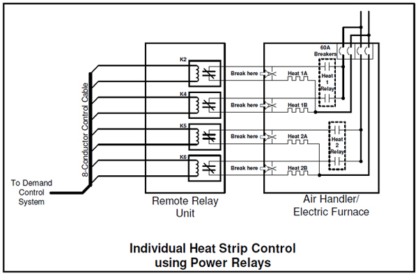
Hookup Auxiliary Heat (Individual Elements) (refers to drawing immediately above)
This wiring should be done by a licensed electrician and is not recommended for homeowners.
- Turn heat element breaker(s) OFF. There is generally more than one breaker on an electric furnace or air handler with electric strip heat.
- Mount a Remote Relay Unit on or near the air handler unit, if required. (Read the Tech Tip on Remote Relay Units for more information)
- Using 10- or 12-gauge wire as required by breaker size and/or load size, rewire one side of each element through a relay in the Remote Relay Unit. Wire one element per relay, if possible, leaving the second, unused relay pole as a spare (if the remote relay unit is equipped with Double Pole relays). If there are five or more elements, wire two elements per relay. (Also see the instructions that come with the Remote Relay Unit.)
- Refer to the Remote Relay Unit instructions to wire the Remote Relay Unit to the control unit.
- When installation is complete, turn ON breaker(s) to air handler or electric furnace.
Note: This type of control is usually done in extremely cold regions, or when individual control of elements is desired. Also see the Tech Tip on Control of Electric Furnaces for Low Voltage Control of Heat Stages.
Control of Heat Pumps: Examples of Priority Hook-ups
| 4-Relay Models Models (Low voltage control for aux. heat) | ||||
|---|---|---|---|---|
| Last Shed | 24-hour control | First Shed | ||
| Relay | 1 | 2 | 3 | 4 |
| Load | Dryer | Compressor | Water Heater | Auxiliary Heat |
| 8-Relay Model or 4-Relay Model with 4-Relay Remote Relay Unit Auxiliary Heat Individual Elements- Line Voltage Control | ||||||||
|---|---|---|---|---|---|---|---|---|
| Last Shed | 24-hour control | First Shed | ||||||
| Relay | 1 | 2 | 3 | 4 | 5 | 6 | 7 | 8 |
| Load A | Dryer | Compressor | Water Heater | 5kW Heat | 5kW Heat | 5kW Heat | 5kW Heat | 5kW Heat |
| To Remote Relay Unit | ||||||||
Caution
In extremely cold areas, the heat pump compressor should be equipped with an outside temperature sensor and be set to lock out the compressor from running whenever the outside temperature is below 35 degrees.